The recent experiments with MOSFET linear amplifiers showed than my collection of 50ohm dummy loads was hopelessly inadequate for high power testing. I will build several 50ohmloads that are suitable for use at frequencies from LF to UHF and at various power levels from milliwatts to kilowatts. We will also explore some very accurate methods of power measurement. The first and perhaps the only component we will need is a 50ohm resistor, which should be a pure 50ohm resistance with no inductive or capacitive reactance. Although you will often see "non-inductive" resistors offered for sale, all resistors have some inductance. Wirewound (WW) resistors are likely to have a relatively high inductance. Carbon composition (CC) types typically have a very low inductance. In some cases, the inductance of the connecting leads at each end of the resistor package might be greater than the inductance of the resistive element.
COMMON RESISTOR TYPES.
Carbon composition resistors are made from a mixture of carbon and an insulating filler material, which is formed into a rod or other suitable shape. A metal connecting lead or cap is fitted to each end of the resistive element. The resistance is determined by the ratio of carbon to filler. The resistor is basically a straight and relatively short carbon rod. Because of its simple construction, this type of resistor has low inductance, typically just a few nH for low wattage types. CC resistors also have good pulse handling capabilities. They are not as stable as more modern resistor types. The value of CC resistors tends to vary over long periods of time, especially if operated at high temperatures. Typical tolerance values for CC resistors are 5% or 10%. Carbon film (CF) resistors are made from similar materials to the carbon composition types. The resistive element is made from a film of carbon, which is applied, to the surface of a ceramic insulator. The most common form of CF resistor is the standard 0.25, 1 or 2W axial leaded resistor. The carbon film on the outer surface of the ceramic insulator has a spiral groove running along the length of the resistor body. The pitch of this groove determines the total length and width of the resistive carbon ribbon. This method of construction allows for easy and accurate trimming of the resistor value during the manufacturing process. Metal film (MF) resistors use a similar method of construction to CF types. The resistive element is a layer of nickel-chrome or other metal alloy, which is deposited on a ceramic insulator, and also has a spiral groove. Modern MF resistors are laser trimmed which gives extremely accurate control of the resistor value. Even standard low cost resistors have a typical tolerance of 1% and tolerances of 0.1% are readily available. MF resistors are less noisy than CF types and they have excellent thermal stability, typically 50ppm/°C. Low power surface mount resistors are usually CF types. Their very small size means they have very low inductance, making them suitable for use well into the microwave region. Wirewound resistors usually consist of a coil of resistance wire wrapped around an insulating core. Some high power types are enclosed in a metal package, which is easily mounted on a heatsink. WW resistors are more than other resistor types. They have many applications in low frequency, high power circuits, but they are not suitable for most RF applications. Power film resistors like the Caddock 9000 series [1] are ideal for use in RF dummy loads. These low inductance resistors are enclosed in a TO-247 plastic package, which is easily mounted on a heatsink. The MP9100 resistor is rated for a maximum dissipation of 100W at 25°C and has a tolerance of 1%. A pair of 100ohm devices mounted on a heatsink and connected in parallel would make an excellent dummy load for use from LF to VHF and beyond.
CHOOSING A RESISTOR.
There appears to be a misconception among some radio amateurs about the suitability of ordinary MF resistors for use in RF dummy loads. Some go to great lengths to find older CC resistors. All this trouble and expense can hardly be justified because cheap and readily available metal film resistors are well suited to this application. The inductance of a typical 2W MF resistor is quite small. There is no simple way of calculating the inductance based on the resistance value. The metal film spiral forms a small inductor. If the metal alloy has a high resistance, the number of turns will be small. If the alloy has a lower resistance, a greater number of turns will be required to achieve a given value of resistance. Stripping the outer protective layer from a random collection of 100ohm, 2W resistors revealed that the number of turns ranges from about 1.5 to 3. For a typical 2W resistor with a diameter of 4.2mm and a spiral length of l0mm, you could expect the inductance of the resistive element to be in the 3-14nH range. Even a QRP dummy load will probably have several resistors connected in parallel, which effectively reduces the overall inductance. The inductance of the metal film spiral appears as an inductance reactance,which is in series with the resistor. Resistors also exhibit a capacitive reactance which appears as a small value (~1pF) capacitor connected in parallel with the resistor. To see how a pair of parallel 100ohm, 2W CF resistors would behave at radio frequencies, I created a QUCS computer model of a dummy load. The resistors were assumed be 99ohm, series inductance of 14nH and parallel capacitance of 1pF. The model shows input return loss of greater than 40dB (VSWR=1.02:1) from 1 to 70MHz, 20dB (VSWR=1.2:1) up to 530MHz and l0dB (VSWR=1.9:1) at 1GHz. A test circuit consisting of two Maplin DI00R resistors soldered directly to the back of a co-axial socket was used to confirm the accuracy of the model. The test circuit showed a perfectly flat SWR from 1-30MHz and a very low SWR of around 1.1:1 at 145MHz. This load should be useful for tests from LF to 2m and perhaps up to 70cm if extreme accuracy is not required.
POWER RATING.
It is a common amateur practice to operate dummy load resistors at power levels above their maximum power rating. This practice is justified by the fact that SSB and CW transmitters have an average power output, which is considerably less than the peak output. Provided that the overload periods are short and not too frequent, metal film resistors can withstand this kind of abuse without suffering any damage. So just how much overload can a 2W metal film resistor take?. Some amateur literature suggests peak powers of more than twice the maximum continuous power rating of the resistor, in line with the established duty cycle of CW and SSB transmitters. I decided to test a few 2W, 1% tolerance resistors to destruction to see how they behave. I used a variable voltage PSU for the lower power tests and the 400W linear PA from last month's Homebrew for the high power RF tests. Running the resistors at twice their maximum rating for periods of 30 seconds caused no damage. Periods of a few seconds at l0W (500%) also seemed to cause no damage. Operating the resistors at l4W (700%) caused the metal film layer to glow red after 20 seconds. After several tests at this level, the room temperature resistance of the resistor was increased to 103ohm (3%) which indicates damage. It would seem that brief periods of operation at 200% are quite safe, especially if low duty cycle modes are used. For the RF tests, the resistors were immersed in oil. Most sources recommend that you use 'proper' transformer oil for cooling dummy loads, but I have had considerable success with ordinary rapeseed cooking oil. A pair of 2W 100ohm resistors were used to make a 50ohm load. The resistors remained cool at power levels, which would have been destructive without oil cooling. The resistors showed no sign of distress after several minutes at 20W (500%). Increasing the power to 100W (2500%) caused the oil to boil on the surface of the resistors, but still caused no damage. Increasing the power to 400W (10,000% overload!) caused a sudden increase in SWR to 2:1 as one of the resistors went open circuit. The fact that it took a power level of 100 times the maximum rating to destroy the resistors illustrates the effectiveness of oil cooling. Some commercially made dummy loads use a single high power 50ohm resistor. The cylindrical resistor is often enclosed in a metal tube so that the resistor body and the enclosing tube form
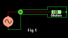 a co-axial transmission line. This improves the performance of the dummy load at UHF where the resistor length is a significant fraction of a wavelength. Figure 1 shows how a resistor can be used to terminate a transmission line with the minimum disturbance to the line impedance. This arrangement was used in the famous Heathkit 'Cantenna' dummy load. The metal tube is arranged vertically so that it acts as a duct for rapid convection of hot cooling oil. The resistor body is a hollow ceramic tube so that cooling oil can also flow through the
centre of the resistor.
If you decide to build an oil-cooled dummy load, there are a few things you should bear in mind. The oil won't stay in the tin forever. Sooner or later, the tin will get rusty or you will drop it and the lid will pop off. You should store it somewhere where it won't do too much damage if it leaks. Always drill at least two breather holes in the lid so it won't burst due to increased pressure when the oil is hot. You are unlikely to boil a couple of litres of oil
with a 100W transmitter, but if you are testing at high power levels, make sure that the load doesn't get too hot or you might end up facing the amateur radio equivalent of a chip pan fire!
A QRP DUMMY LOAD AND WATTMETER.
Figure 2 shows a dummy load made from three standard 150ohm 0.25W resistors. A diode detector is used to measure the peak voltage across the load.
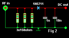 The diode should have a very fast switching speed and a low forward voltage drop. The IN5711 Schottky diode is an ideal candidate for the job. Point contact Germanium diodes like the 1N34A are also quite suitable for use in this circuit. To keep stray inductance to an absolute minimum, the load resistors and detector diode are mounted directly on the back of an N connector. To keep diode current and forward voltage drop as low as possible, the DC voltage should be measured with a DMM or other high resistance voltmeter. The circuit is designed to work at a power level of up to 1W (+30dBm) or l0V peak. Assuming that the RF input is a sine wave, the average power delivered to the resistor is the RMS voltage squared, divided by the load resistance, or (Vpeak*O.7071)²/50.
DIODE DETECTORS.
Simple diode detectors are not linear. There is a small forward voltage drop across the diode, and this voltage varies with diode current. Even if we allow for a fixed voltage drop across the diode, measurements will not be accurate at all power levels. At 1mA of diode current, the drop across a Schottky signal diode will be about 0.3V. At very low diode currents of around 1µA the drop will be much lower, typically about 0.1V. This is not too much of a problem at higher power levels because an error of a fraction of a volt is quite a small percentage of a total peak voltage of several tens of volts. We can choose to ignore it or partially compensate by adding a fixed offset to the measured value. About O.6V for a silicon diode or O.3V for a Schottky signal diode such as 1N5711 or BAT 43 is close enough to be reasonably accurate. However, at very low power levels, the voltage drop is a significant fraction of the peak voltage and will lead to increasing errors as the peak voltage is reduced. For example, if the peak voltage is 500mV (+4dBm, or 2.5mW), a voltage drop of 0.2V across the detector diode would result in a measured peak voltage of just 300mV (0.46dBm, or 0.9mW). This problem gets even worse when the peak voltage input approaches 0.1-0.2V and the detector output voltage is close to zero.
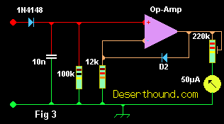 There are a number of ways to improve the accuracy of a diode peak voltage detector. We could calibrate the meter by hand to eliminate errors at the lower end of the scale. This approach works well in practice but it is time consuming and requires unique calibration curves for individual diodes. We could apply a small amount of forward bias to the diode which would reduce the voltage drop for RF signals or we could use a second identical diode as a reference to show us the required offset for a given level of current and diode temperature. It would be possible to apply all three methods to obtain the best possible accuracy but to keep things simple; I will adopt only the last method. Figure 3 shows how an opamp and a second diode can be arranged to compensate for the voltage drop of the detector diode. This circuit is due to KI6WX [2]. When used with a closely matched pair of 1N5711 diodes, this circuit will accurately track the input voltage down to a level of well below 0.1 V (-10dBm, or 100µW). If the circuit is to be used with a single-ended power supply, the opamp input and output voltage range must go all the way down to the negative supply rail. I used one half of an LM358. A CMOS input type like the CA3140 would be capable of even better performance.
DIODE VOLTAGE.
At first glance, it might appear that the detector diode only needs a peak inverse voltage rating which is just slightly higher than the peak RF voltage.
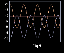
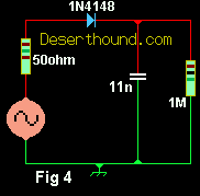 Figure 4 shows a QUCS simulation of a peak voltage detector, which is similar to the circuit described earlier. After the first few cycles of RF, Cl is charged up to a value that is almost equal to the peak input voltage. This means that on negative excursions of the input sine wave, the voltage across the diode is twice the peak value. Figure 5 shows the input voltage (blue), diode voltage (red) and DC output voltage (purple) for a 1W input. Bear this in mind when you are selecting a diode for a high power dummy load. Diodes with a high PIV rating are available, but most of them are high power, low frequency devices that are not suitable for use at RF. It is possible to use several standard low voltage diodes connected in series to increase the total PIV rating,
  but this will increase the voltage drop across the diodes. Some higher voltage devices like the BAV21 switching diode have a PIV rating of 250V and are just about fast enough to be useful up to 30MHz, but they probably won't be useful at VHF. Ultra fast Schottky devices are like the 1N5711 are useful into the microwave region and have a PIV rating of 70V. If necessary, a resistive voltage divider can be used to reduce the peak voltage to a level that won't damage the diode. A 20dB coupler of the type described in the directional wattmeter project [3] is another way of reducing the peak voltage to a safe level.
AN LF TO 2GHZ 250W DUMMY LOAD.
Special flange mounting RF metal film resistors like the Florida RF 32-1037 make an ideal resistor for a dummy load. This device has a maximum dissipation rating of 250W and an SWR of less than 1.15:1 from LF up to more than 2GHz. Apart from the resistor, all you will need is a large heatsink, an N-type or similar RF connector and a small dab of heatsink compound. Suitable resistors are available on Internet auction sites from time to time. I purchased mine on eBay for a price of $24.
A QRO HF DUMMY LOAD.
100ohm power resistors for use in Wilkinson power splitters are often available at low cost. A pair of these resistors will make an excellent dummy load. I recently acquired a
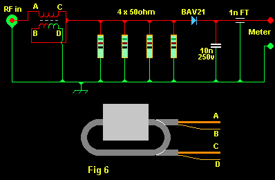 power film resistor which has four 50ohm resistors mounted on a large copper heatsink
flange. As all of the resistors are connected to the mounting flange at one end, it was not possible to connect the resistors in a series/parallel combination to make 50ohm. The solution was to connect the four resistors in parallel to make a 12.5ohm load and use a 4:1 transmission line transformer to provide a 50ohm match. The transformer consists of two turns of RG58 on a Maplin N90AB ferrite core. This gives a perfect 1:1 SWR from 1.8 - 30MHz. The finished circuit is in Figure 6. Note that the DC voltage from the diode is only half the peak-input voltage because of the 2:1 voltage ratio of the transformer. I haven't been able to make much of an impression on this load during testing. Several minutes of SSB speech at 500W PEP will bring it from room temperature to lukewarm. I'm sure my transmitter would catch fire long before this load gets hot!
ANOTHER APPROACH.
I have seen various reports [4] about radio amateurs using salt water as an RF dummy load. For my first experiment, I made a small dummy load using a 750ml orange juice bottle as the container. I drilled a hole in the cap for a BNC connector and a small hole as a breather. Two lengths of 1.7 diameter copper wire were connected to the BNC socket and the bottle was fill almost to the top with clean water. The wires should be long enough to almost reach the bottom of the bottle, carefully spaced so that they can never touch. A very small amount of ordinal table salt was added to the water (a fraction of a teaspoon) until my SWR meter read 1:1 at 29MHz. The DC resistance of the load is still several k? so I assume that this load works as a short length of transmission line with extremely lossy dielectric. I was delighted to find that the SWR was better than 1 from 1.8 - 30MHz and only rises to 1.2:1 at 145MHz! This load was tested at 400W PEP SSB on HF for several minutes.After this test, the bottle was quite warm but not excessively hot. In a moment of extreme bravery (foolishness) I put an extra large fan on the heatsink of my 2m MOSFET PA, set the output to l00W I put a brick on the Morse key. After 10 minutes, the load was quite hot, but not too hot to touch. Happily, the 2m PA survived the test. A larger version using 1.5l kitchen storage jar and an N-type connector can be used. This shows a flat SWR from 1.8 – 30MHz, rising to 1.7:1 at 145MHz I'm sure I will never be able to overheat this one with my puny little transmitter but I do know that my 3kW rapid-boil kettle takes about 3.5 minutes to boil 1.5l of water. I don't know how long the copper wire and RF connectors will survive in a jar of salt water but they still looked good after a week and I have plenty of spare they do fall apart in the months ahead