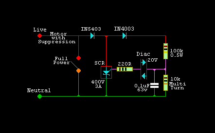
Here is a simple circuit I use for an electric drill. Unlike many speed control circuits in modern drills, this one gives reasonably constant speed under high torque.
But it does suffer from speed variation due to mains fluctuations.
It is only suited for AC/DC (e.g. brush) motors, & must not be used on AC Induction motors!

PARTS
My drill motor was only 500 Watt so...
   D1 is 1N5403 (50A peak), D2 is 1N4003
   C is a 0.1uF (63v)
   DIAC any 20V device (higher voltage = less control at low RPM.)
   220R is optional depending on the sensitivity of the SCR.
   SCR is a 3A 400V device (50A peak) it can be a Triac as D1 inhibits wrong
       way conduction. (mine used to blow up until I added the diode.)
   The switch shorts out controller for full AC Power.
   Multi turn low speed control is a preset pot in my design, but can be a
   properly insulated control (slider etc).
TRIGGERING
The DIAC is a 20-30V (20V on 110V) device, when the 0.1uF cap charges up over its' strike voltage, the 0.1uF charge is dumped into the SCR gate. I have seen low voltage transistors used as instead of a diac, when they avalanche they produce a similar action, provided the current is not excessive.

HOW IT WORKS
This circuit attempts to put DC out to the motor 50 times a second, every other half cycle (variable up to half power mode). How much DC depends on the preset setting & the motor back e.m.f.
Hence the power/torque has some speed feedback feature unlike the normal phase control type, & it enables variable torque loads to be handled much better, without dramatic R.P.M. changes.
With heavy torque loads, always cool off a drill at high speed occasionally to get the cooling fan to do it's job, otherwise you will cook the motor.